
MiruRLB - Smart USB relay board for Raspberry Pi (USD $149.90)
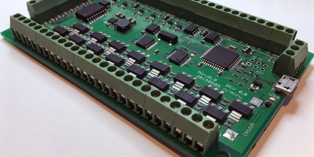
The advent of the Raspberry Pi, a full blown low cost Linux System on a small footprint circuit board, does provide the necessary environment to implement all sorts of home automation controllers that are as open and connectible as you make them. The only thing that is missing is a more versatile hardware interface to equipment like power relays, sprinkler valves, pool valves, smart pumps and sensors.
The MiruRLB is a controller board which is meant to bridge the gap between physical hardware and software allowing alternate solutions for home automation controllers.
Hardware
Pool valves, as well as sprinkler valves, run on 24VAC, the MiruRLB has outputs that can turn that
voltage on or off under software control, provides sensor interfaces with translation of measurement
results and 'knows' how to talk to 'smart' pumps.
The current I/O features are:
- 16 24VAC relay outputs, that can be configured in pairs for pool valve operation
- 8 open collector outputs for high side 12VDC relays
- One wire bus interface for DS18x20 temperature sensors
- I2C master interface (5V) for sensor expansions
- 4 analog inputs for pressure sensors, PH probes or ORP probes
- 3 digital sensor inputs, one configured to handle a ping sensor for level measurements
- RS485 interface, used to communicate with 'smart' pumps
- real time clock with backup battery holder
- remote spa interface, it handles a 'standard' spa remote with 4 buttons and a LED, it is used in many pool/spa installations
The MiruRLB communicates with a host processor through USB. The host is envisioned to be a computer of some kind running one of the popular operating systems and capable of 'running the show' by means of one or more programs. It is expected that a program on the host can do all the interfacing with the Internet. The firmware of the MiruRLB is not Internet aware nor has access to resources to do it.
Software for the Raspberry Pi
The software for the MiruRLB is implemented as firmware on the MiruRLB and a server/client program that needs to run on the host of the USB port the MiruRLB is connected to. The software for the MiruRLB comes in a ZIP archive with the name rlbXXX.zip, where XXX stands for the revision of the archive. The installation is done by unzipping the archive, changing directory and running an install script.
The first time around the system is not aware of the MiruRLB, subsequent installations will check and update the firmware of the MiruRLB with the help of 'avrdude', which you need to install if you want to update the firmware.
To Linux the MiruRLB is an USB device, it enumerates it as a serial device. The MiruRLB firmware emulates a device that is recognized by Linux as a ttyUSB*. To help identifying the MiruRLB the firmware uses a distinct 'bcdDevice' identifier of 0x0802. This can be detected by the udev system of Linux. The installation adds a udev rule file to the system that will map a MiruRLB to a specific device.
Server/Client rlb
The rlb server/client comes as a precompiled binary for the RasperryPi. In a single relay board installation rlb as a server will write logfiles in directory /var/log/rlb if it exists and is read/write accessible by the server application. The rlb server generates a log file for every day, the file names are formed from the date as yymmdd.log.
When the rlb server is running the rlb program can be used as a client to the server. This means, using the rlb command will contact the running server to fullfill the request. The command 'rlb s' will retrieve the status of the relay board.
Use the rlb client to issue commands to the relay board from a PHP web application. The distribution of the software has a web server example you can study and run to get a basic idea on how it is intended to work.
The rlb server has a UDP command port (13330) intended to be used by the client and/or a controller application. An application can sign up to receive all messages from the relay board as they occur. This is referred to as the 'asynchronous' interface.
An application creates a datagram socket and sends a two byte message (0x07 0x00) to the server port.
The server will respond with a two byte message (0x06 0xnn). From now on the server will relay any
message from the relay board to that socket.
From time to time the server will check if the receiving end of a socket is still alive. To do that it will
send a two byte message (0x05 0x00) and expects a two byte message back (0x06 0x00). If there is no reply to
the 0x05 message, the server will drop the socket from its distribution list.
To disconnect 'orderly' from the server distribution list send the following two bytes (0x7f 0x00),
the server will respond with (0x06 0x00).
The server sends a (0x04 0x00) message to all sockets on its
distribution list before it exits.
An application can send a (0x07 0x01) message the server to get on the distribution list for the next message from the relay board. The socket goes off the distribution list as soon as a message is sent. This is the equivalent of a 'long poll' request.
Here is the Documentation.

Web interface example
Here is an example how the userinterface could be implemented with the help of a webbrowser on a PC or smartphone and the webserver on the RaspberryPi. Note by using a webpage for interacting with the user there is no need to write a native application for the userinterface of the system.
The webpage on the left is implemented using HTML, CSS, JavaScript and PHP. The communication from the webpage to the rlb client server is done via messages to the PHP code on the webserver (AJAX mechanism). The webpage also makes use of long poll requests to the server to render status changes when they become available. This way the webpage can keep up to with what is happening on the board.
The example code for the webpage shows how the various mechanisms can be used to generate an adequate userinterface. It is important to realize that sending instuctions and rendering status are asynchroneous operations. For example, to turn a relay on it is bad practice to send the instruction and render the relay marked on. The example code sends the instruction and relies on the status report to render the relay status. This way the webpage will show the actual status of the relay, even if it gets activated by a different controller.
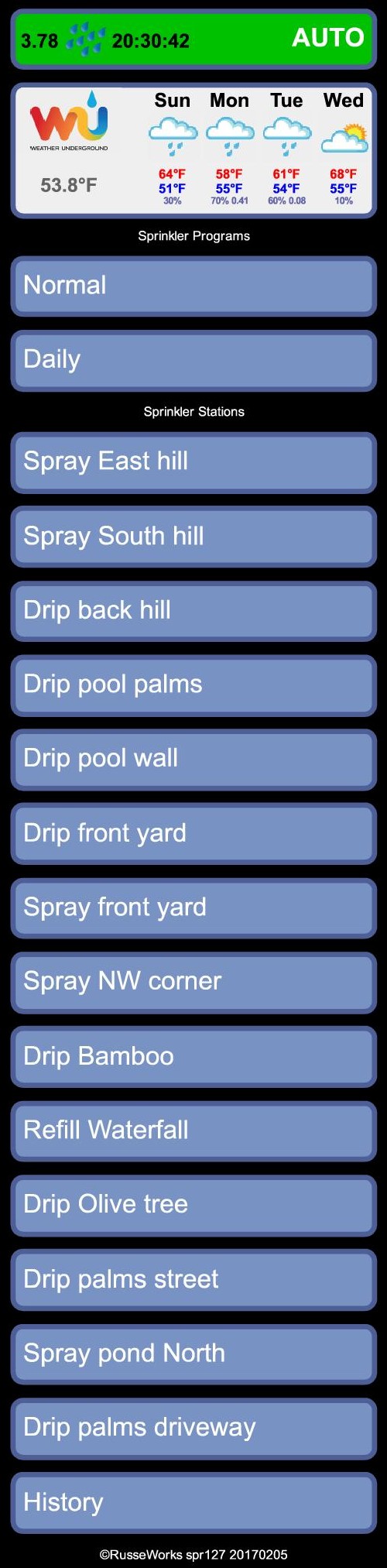
Sprinkler System Example
Here is an example how the userinterface of a sprinkler system could be implemented with the help of a webbrowser and the webserver on the RaspberryPi.
The controller program on the RaspberryPi can be implemented in any language as long as the environment allows the use of sockets to communicate with the webserver.
MiruPCB - Wi-Fi less control of Parrot AR.drone (USD $59.90)
The original project was started in 2011 by a discussion on www.rcgroups.com (nosaari). The project used at first an Arduino PRO/MINI connected to a RC-receiver to overcome the range limitations of the Wi-Fi based Parrot AR.drone. A new thread www.rcgroups.com (miru) was started to answer specific questions on 'how to do it'. When the new AR.drone (version 2) came out it became evident that the MiruMod would have to use a logic level converter to communicate with the drone.
After a while the thread became fairly large and it was hard to find specific information. A good soul created the website www.mirumod.net to summarize the information.
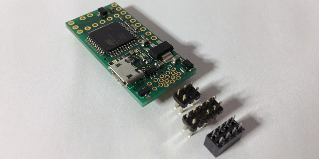
The MiruPCB combines an ATMEL32U4 processor with a logic level converter for the MiruMod on a single circuit board. By using a processor with separate serial and USB ports it is possible to use the MiruPCB as a serial bridge to the AR.drone.
Here is the Documentation.
Consulting
RusseWorks provides consulting services for hardware and software projects:
- Hardware design, from concept to prototype
- Circuit board design
- Circuit board layout
- Circuit board prototype fabrication
- Small production runs
- Software design, from concept to implementation
- Standalone controllers
- Linux based controllers
- Coding support in C, Assembly, HTML, CSS, JAVA and PHP
The products on this website have all been designed and realized by RusseWorks. These are inhouse projects that touch on many different design capabilities.
About RusseWorks
RusseWorks was founded to provide an outlet and contact point for designs of electronic hardware and software that make sense following the KISS principle. The trigger point was a discussion about WiFi-less control of a Parrot AR.drone realizing that people make things way too complicated due to lack of knowledge or research time and not having access to the skills of an experienced hardware/software engineer.